


News & Projects
Thermosyphon oil cooling: how it works and how to size it
A thermosyphon cools screw compressor oil with no pump and no fan: the only driving force is a liquid head, so the whole method comes down to sizing that head correctly. Here is how it works, how to size it with a worked example, and the mistakes that stop a thermosyphon from working.
Why screw compressor oil needs cooling at low temperature
In a screw compressor, oil is injected into the compression process: it seals the rotors, lubricates the bearings and absorbs a large share of the compression heat. At −40 °C evaporating and +40 to +45 °C condensing, the compression ratio is high and the discharge temperature rises quickly.
Without cooling, the oil loses viscosity, the bearings suffer and the compressor trips on its safety devices. A heat load of around 8 to 15 kW per compressor, in the examples below, has to be removed continuously.
There are three options:
| Option | Principle | Drawback |
|---|---|---|
| Liquid injection | Liquid is injected into the screw to limit the discharge temperature | The injected refrigerant is compressed again: loss of cooling capacity and efficiency |
| Air- or water-cooled oil cooler | Dedicated oil/air or oil/water heat exchanger | A fan or water loop to power and maintain |
| Thermosyphon | Liquid refrigerant from the receiver evaporates in a plate heat exchanger; the vapour returns to the condenser | Requires a liquid head and careful pipe routing |
A thermosyphon rejects the oil heat at the condenser, at condensing temperature, with no penalty on cooling capacity. It is our preferred option on low-temperature screw compressor racks.
How a thermosyphon works
The loop runs on the density difference between a column of liquid and a column of liquid/vapour mixture.
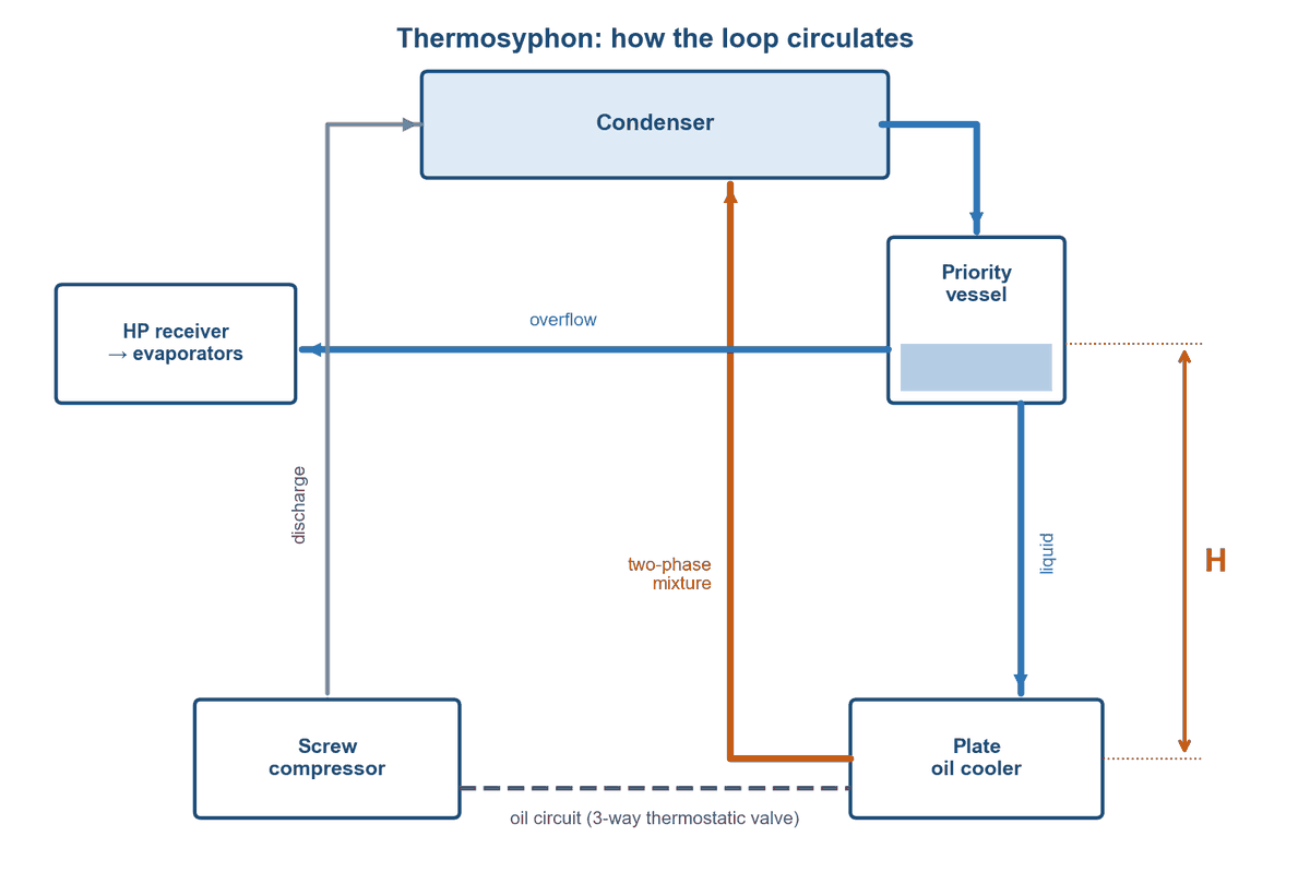
How the loop circulates: the liquid head H between the priority vessel level and the oil cooler is the only driving force.
- Condensed liquid fills a priority vessel located above the oil cooler.
- It flows down by gravity to a plate heat exchanger (the oil cooler) at the low point.
- In contact with the hot oil, part of the liquid evaporates.
- The lighter liquid/vapour mixture rises back to the vessel or the condenser.
- The vapour is condensed again with the compressor discharge gas, and the cycle starts over.
The vessel is called a priority vessel because the oil cooler draws from it first: only the overflow goes on to the main receiver and the evaporators. The oil is therefore never short of cooling, even when the system is short of refrigerant.
On the oil side, a three-way thermostatic valve bypasses the cooler while the oil is cold, so it is not overcooled at start-up or in winter.
This is where the difficulty lies: the only driving force is the liquid head H. If it does not overcome every pressure drop in the loop, circulation stops and the oil overheats.
Sizing method in 5 steps
The calculation is iterative: estimate the pressure drops, derive the head, then check again with the pipe sizes actually chosen.
1. Oil heat load. It comes from the compressor manufacturer’s selection software, at the worst operating point (maximum discharge temperature).
2. Refrigerant mass flow to the oil cooler. Enthalpies are taken at high pressure (condensing temperature).
ṁOC = Qoil / (hdew − hbubble)
3. Volume flows, at a circulation rate of 1.5 (50 % liquid overfeed; up to 4 with NH3).
Vliq = 1.5 × ṁOC × vliq
Vreturn = ṁOC × vvap + 0.5 × ṁOC × vliq
4. Pipe sizes chosen to stay within the reference velocities: 0.3 to 0.8 m/s in the liquid line, a few m/s in the vapour return line (see the table below).
5. Minimum liquid head H, with a safety factor of 1.1 to 1.25 on the total pressure drop (liquid line, heat exchanger, vapour return line, and the condenser when it is part of the loop).
H ≥ (1.1 to 1.25) × ΣΔp / (ρliq × g)
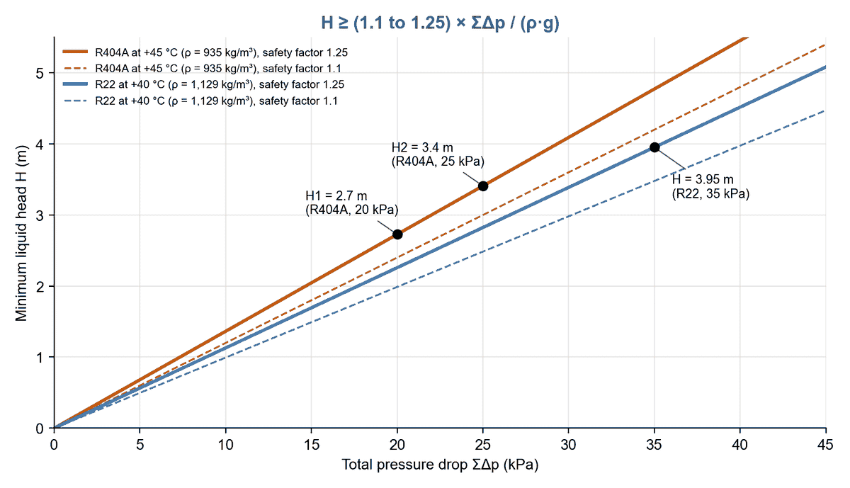
Minimum liquid head H versus total pressure drop, with the three BITZER examples.
The actual pressure drops are then recalculated with the selected pipes, bends and valves. If the available head is no longer enough, increase the pipe sizes or raise the vessel, and repeat.
Worked example: 3 screw compressors, R404A, −35 / +45 °C
To remove 23.7 kW of oil heat, the oil cooler needs 758 kg/h of refrigerant and about 2.7 m of liquid head. The example follows the calculation method published by BITZER for the standard thermosyphon cycle.
Data: 3 screw compressors with economiser, −35 °C evaporating, +45 °C condensing, R404A, total oil load 23.7 kW (discharge temperature 80 °C).
Properties at +45 °C: liquid density 935 kg/m³, vapour specific volume 0.00851 m³/kg, Δh = 381.10 − 268.51 = 112.59 kJ/kg.
| Step | Calculation | Result |
|---|---|---|
| Mass flow | 23.7 × 3600 / 112.59 | 758 kg/h |
| Liquid to the heat exchanger (rate 1.5) | 758 × 0.00107 × 1.5 | 1.22 m³/h |
| Vapour + liquid return | 6.45 + 0.41 | 6.86 m³/h |
| Liquid line 28 mm (25 mm ID) | 1.22 m³/h | 0.69 m/s |
| Return line 28 mm (25 mm ID) | 6.86 m³/h | 3.9 m/s |
| Circuit 1 vessel / heat exchanger: ΣΔp | 15 + 5 kPa | 20 kPa |
| Head H1 | 1.25 × 20,000 / (935 × 9.81) | 2.7 m |
| Circuit 2 condenser / vessel: ΣΔp | 20 + 5 kPa | 25 kPa |
| Head H2 | 1.25 × 25,000 / (935 × 9.81) | 3.4 m |
The calculation covers two circuits: H1 between the vessel and the heat exchanger, H2 between the condenser and the vessel. The BITZER document rounds H2 to 3.3 m; the exact calculation gives 3.41 m, which we round to 3.4 m. In a second BITZER example (2 screw compressors, R22, −40 / +40 °C, 29.7 kW of oil heat, priority vessel), the single loop adds up to 35 kPa of pressure drop and requires 3.95 m of head.
Reference values
These orders of magnitude are a starting point for the calculation; they must be confirmed project by project.
| Criterion | NH3 | R22 | R404A / R507A |
|---|---|---|---|
| Liquid line velocity to the heat exchanger, full load (m/s) | 0.3 to 0.8 | 0.3 to 0.8 | 0.3 to 0.8 |
| Vapour return velocity, full load (m/s) | 5 to 10 | 4 to 8 | 3 to 6 |
| Liquid reserve in the vessel (litres per kW of oil load) | 0.3 | 0.9 | 1.4 |
| Circulation rate through the heat exchanger | 1.5 to 4 | 1.5 | 1.5 |
| Safety factor on ΣΔp | 1.1 to 1.25 | 1.1 to 1.25 | 1.1 to 1.25 |
Source: BITZER “Thermosyphon Oil Cooling” calculation documents, values given as a guide by the manufacturer.
Our field application: 44.2 kW screw compressor at −43 °C
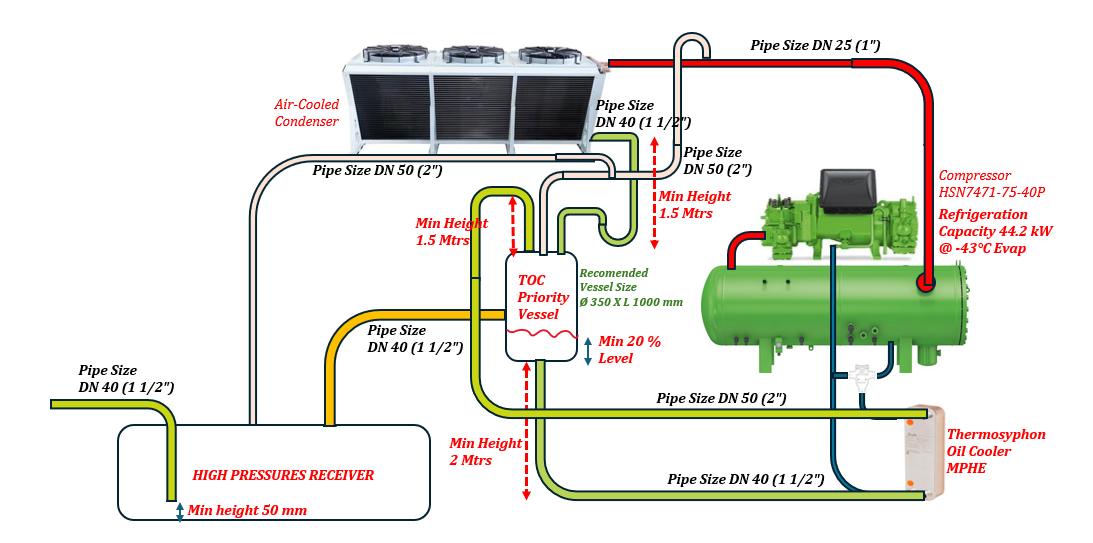
On a recent installation, we applied this method to a BITZER HSN7471-75-40P screw compressor rated at 44.2 kW of cooling capacity at −43 °C evaporating, with an air-cooled condenser.
The key design choices:
- Dedicated priority vessel, ø 350 × 1,000 mm, between the condenser and the high-pressure receiver, with a minimum liquid level of 20 %.
- At least 2 m of head between the priority vessel and the plate oil cooler, fed through a DN 40 (1 1/2″) line; liquid/vapour return in DN 50 (2″).
- At least 1.5 m between the condenser outlet and the priority vessel, and 1.5 m on the vapour riser to the condenser.
- Gooseneck on the compressor discharge (DN 25) before the condenser inlet, so that liquid cannot drain back to the compressor.
- DN 40 overflow to the high-pressure receiver: the oil cooler is always served first.
- Danfoss D62L-H80 plate oil cooler (code 021H0865): 31.73 kW of oil cooling according to the Danfoss selection with R404A, refrigerant entering at +36 °C and oil cooled from 85 to 55 °C.
The schematic below shows these dimensions.

Installation schematic: air-cooled condenser, priority vessel, plate oil cooler and BITZER HSN7471 screw compressor.
Common mistakes
Most thermosyphons that “don’t work” have too little head or a poorly routed vapour return line.
- Head calculated without a safety factor. With no margin, the smallest overlooked pressure drop (a bend, a valve) stops circulation. The 1.1 to 1.25 factor is not optional.
- Heat exchanger pressure drop ignored. The plate heat exchanger must be selected for a low refrigerant-side pressure drop (around 0.1 bar).
- Low points in the return line. The mixture must rise continuously; a liquid pocket in a horizontal section adds back pressure.
- Return connected in the wrong place. It must join the top of the vessel or the condenser inlet, never a point at higher pressure.
- No liquid reserve. Without a priority vessel, the oil cooler loses its feed as soon as the system charge drops.
- No thermostatic valve on the oil side. The oil is overcooled at start-up or in winter, and its viscosity becomes too high.
- Calculation done only once. The final pipe sizes, bends and valves change the pressure drops: the calculation has to be checked again.
In short
A well-sized thermosyphon cools the oil of a low-temperature screw compressor with no pump, no fan and no loss of cooling capacity. Everything depends on a liquid head calculated with a margin, a priority vessel and a vapour return line that rises continuously.
Liquid injection or thermosyphon on your low-temperature screw compressor racks? Afric Froid designs and installs refrigeration racks and selects the right plate heat exchangers. Our engineering team can check the sizing of your oil cooling circuit: contact us. For condensers on coastal sites, see also our article on fin corrosion protection.


